Quality is corrected while you print?
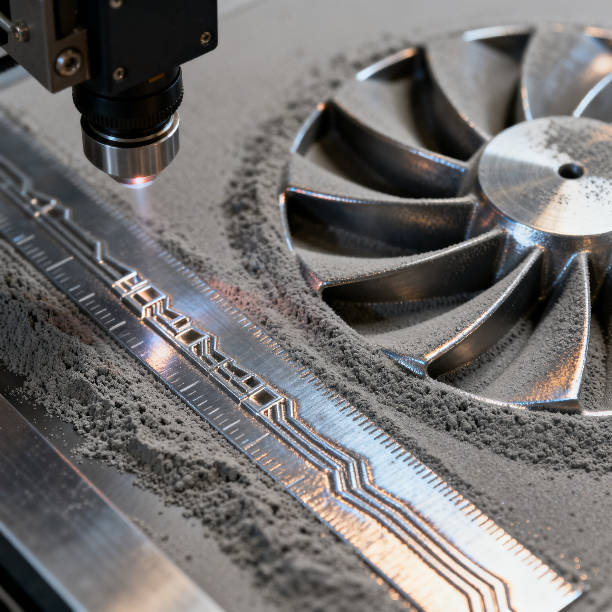
In industrial additive manufacturing, quality control is migrating from the final measurement bench to the printing chamber. Intelligent systems compare each layer with the CAD model and correct deviations in real time, reducing waste and post-processing on complex geometries.
The problem is well-known: post-print inspections can account for more than half the cost of a qualified metal component. On large or complex geometries, such as aerospace structures, inspection becomes physically impossible without destroying the part. Two recent patents propose complementary solutions to move quality control from the metrology lab to the machine itself.
Correct the part while printing
The European patent introduces calibration elements printed next to the actual part to test critical geometries in advance and correct parameters before it is too late.
As described in the patent “Real-time quality assurance”, the system inserts calibration elements into the CAD model, placing them in the free spaces around the component. These elements replicate the critical features of the final part, such as thin holes or intricate cavities, but are printed earlier, at lower heights.
Optical or thermal sensors continuously monitor these calibration elements during construction. The software compares the acquired data with historical data of successful prints. If it detects deviations, the system automatically adjusts the printing parameters: laser power, scan speed, distance between passes, beam offset.
During the printing of a turbine blade head, the system detects a thermal deviation on a calibration element that replicates a cooling channel. The software reduces the laser power for that area, avoiding porosity in the actual component that will be printed in subsequent layers.
The patent also provides for the printing of multiple identical elements in a time sequence. The system can iterate corrections on each element until optimal parameters are reached, or stop the process if deviations exceed predefined thresholds.
This logic exploits two unique advantages of additive manufacturing: the free space around the part and the time available between the start of printing and the construction of critical geometries. Monitoring can be continuous, layer-by-layer, or at preset intervals, with all data tagged to the sample and production parameters.
Continuous comparison with the CAD model
The US patent compares in real time the topology of each deposited layer with the theoretical shape expected from the CAD, automatically correcting geometric deviations layer by layer.
As proposed in the patent “In-situ model comparison”, a topological monitoring system acquires data on the actual surface position of each newly deposited layer. The software calculates the real position and compares it with the position modeled in the CAD.
If it detects a difference, the system intervenes on the deposition parameters of the next layer. It can adjust the laser beam trajectory, the amount of powder delivered, or the energy applied to compensate for the detected error.
Layer-by-layer correction cycle
- Deposition: the system deposits a layer of powder and fuses it with the laser.
- Scan: a topological monitoring system acquires the 3D shape of the newly created surface.
- Comparison: the software calculates the difference between actual position and CAD model.
- Correction: if necessary, the system modifies the parameters for the next layer.
This technology is based on laser scanning systems already present in powder bed machines. The comparison algorithm is scalable and does not require structural modifications to the machine. The main advantage is the reduction of post-processing: greater dimensional accuracy already in printing means fewer subsequent mechanical operations.
Throughput improves by avoiding repetitions for unmet tolerances. Instead of discovering at the end of printing that a part is out of specification, the system corrects deviations while building the component.
Trade-off and operational limits
Both technologies offer tangible benefits but require specific validations for each geometry and introduce complexity in CAD setup and data management.
The calibration system described in the first patent requires designing and positioning test elements for each new type of component. A CAD library of calibration elements selectable based on the critical geometries to be tested is needed. This increases the complexity of the initial setup.
The patent itself highlights the need for extensive validations for each new calibration geometry. It is not clear how long this qualification phase takes nor how transferable the experience is from one component to another.
| Appearance | Benefit | Operational limit |
|---|---|---|
| CAD setup | Reusable elements from library | Validation required for each geometry |
| Data management | Sample tagged data and parameters | High data volume to archive |
| Cycle time | In-process corrections avoid rework | Possible delay between scanning and correction |
For the CAD comparison system, the patent does not specify the computation time required between scanning and correction. On complex or high-resolution geometries, this delay could slow down the process. It also requires precise calibration between the CAD model and in-situ scanning to avoid false positives.
Both systems use already available technologies: optical and thermal sensors for the first, laser scanner for the second. They do not require expensive infrastructure, but integration into the production flow requires specific skills and qualification procedures still to be standardized.
The flexible monitoring provided by the first patent (layer-by-layer, at intervals or continuous video) generates large volumes of data. Adequate storage capacity and analysis systems are needed to manage this information in a traceable manner.
These technologies do not eliminate final quality control, but anticipate it. They shift part of the’inspection from post-process to in-process, with a direct impact on scrap and finishing times. For components with intricate geometries, internal channels or structures not inspectable from the’outside, the value is immediate.
The’aerospace industry, where post-print inspections are particularly burdensome, could benefit first from these systems. More work is still needed to standardize qualification procedures and reduce the complexity of the initial setup. For those working with complex geometries, evaluating the’integration of in-situ systems could mean reducing finishing times by 30%, as suggested by the benefits described in the patents.
article written with the help of artificial intelligence systems
Q&A
How does the European patent for real-time correction during printing work?
The European patent involves printing calibration elements next to the actual part, positioned in the free spaces around the component. Optical or thermal sensors monitor these elements, which replicate the critical characteristics of the part, comparing the acquired data with previous successful prints. If deviations are detected, the system automatically adjusts printing parameters, such as laser power and scanning speed, before the actual critical geometry is built.
What is the principle of the US patent for in-situ quality control?
The US patent compares the topology of each deposited layer in real time with the theoretical CAD model. After deposition and scanning of the newly created surface, the software calculates the differences and intervenes by modifying the parameters of the next layer, such as the laser trajectory or the amount of powder dispensed. This allows geometric deviations to be corrected layer by layer, reducing the need for post-processing.
What are the main advantages of moving quality control from the post-printing phase to the printing chamber?
Moving quality control in-process significantly reduces scrap and costly post-print inspection processes, which can exceed half the cost of a qualified metal component. It also ensures greater dimensional accuracy during the build, decreasing subsequent machining operations and improving production throughput. It is particularly useful for geometries that cannot be inspected from the outside without destroying the part.
What operational limits and trade-offs do these in-process quality control technologies present?
Both technologies require specific validation for each new geometry and increase CAD setup complexity, with the need for calibration element libraries or precise calibrations between model and scanner. Data management is burdensome due to the large volumes generated by monitoring, while on complex geometries there may be a delay between scanning and correction. They also do not completely eliminate final quality control.
For which types of components and industrial sectors are these technologies particularly advantageous?
These technologies offer maximum value for components with intricate geometries, internal channels, or structures that cannot be inspected from the outside, such as in the aerospace sector. In these cases, post-print inspections are particularly burdensome or physically impossible without damaging the part. The integration of in-situ systems can reduce finishing times by up to 30% on these types of components.