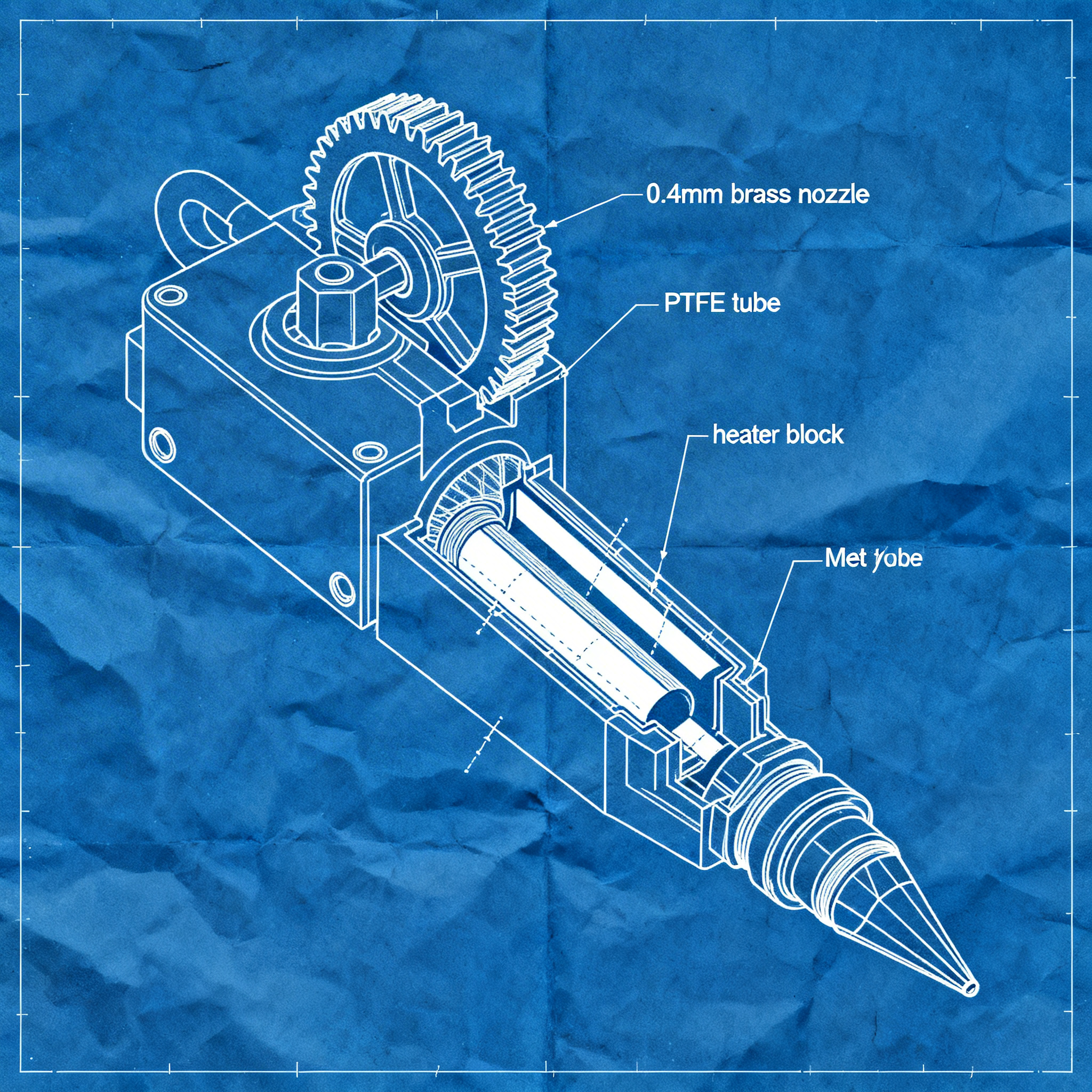
Nozzle and Gcode: Advanced Techniques for Precision in 3D Printing
Optimizing the nozzle and adapting G-code commands is essential to obtain precise and repeatable prints, both in industrial and maker settings. Correct configuration of the nozzle diameter, combined with conscious management of positioning and extrusion commands, makes it possible to prevent common defects such as under-extrusion, over-extrusion, and collisions during printing. This article provides an operational manual for configuring these critical parameters, with advanced techniques ranging from extruder calibration to print path simulation.
Nozzle Configuration for Different Materials
The choice of nozzle diameter and its configuration directly influence print quality, production time, and component wear. Understanding how to adapt the nozzle to the material used is essential to maximize precision and durability.
The standard nozzle diameter is typically 0.4mm, but the choice can vary significantly depending on the application. For fast prints or materials requiring high flow, one might consider a 0.8mm nozzle, while for fine details, smaller diameters such as 0.2mm or 0.3mm are chosen.
An interesting case emerges from experimentation with G-code designed for 0.8mm nozzles used on a 0.4mm nozzle: the result produces a fabric-like texture, with a “fuzzy” feel to the touch, demonstrating how cross-compatibility can generate unexpected aesthetic effects. However, for industrial applications requiring dimensional precision, it is essential to use the correct diameter specified in the G-code.
In the food sector, where 3D printing is finding growing applications, custom nozzles can be designed and printed in food-safe materials in a single day, eliminating complex assemblies and traditional delivery times. This approach demonstrates how additive manufacturing is ready for food production, with one-piece nozzles that ensure hygiene and ease of cleaning.
For ceramic printing or with viscous materials, nozzles with widths of up to 5mm, with particular attention to flow regulation on non-planar geometries: it is necessary to reduce flow on internal curves to compensate for the variation in path length.
Extrusion Management with Advanced G-code Commands
Precise control of extrusion through specific G-code commands prevents printing defects and ensures uniform material deposition. Correct calibration and appropriate use of temperature and extrusion commands are the basis for professional results.
The command G1 E controls dynamic filament extrusion. For example, `G1 E10 F800` extrudes 10mm of filament at a speed of 800mm/min during axis movement. This command is essential when working with layer height variations (variable layer height), where the system must automatically calculate the extrusion amount based on path length, nozzle diameter, and current layer height.
To avoid under-extrusion or over-extrusion problems, it is essential to calibrate the E-steps (extruder steps). This calibration determines how many stepper motor steps are needed to extrude exactly 1mm of filament. Incorrect calibration can cause thin walls, poor layer adhesion, or material buildup.
Temperature control is performed through two main commands:
- M109 S200: waits for the hotend to reach 200°C before starting printing (wait mode)
- M104 S200: starts heating without waiting for the target temperature to be reached
For complex prints with continuous Z variations, it is crucial to implement an adaptive flow rate that compensates for differences in speed and path length, preventing material buildup or shortages during transitions between vertical and horizontal movements.
Positioning Modes: G90 vs G91
The choice between absolute and incremental positioning determines how the printer interprets coordinates in movement commands. Understanding when to use each mode is essential for precise prints, especially on complex vertical movements.
The command G90 activates absolute positioning, where each coordinate represents a precise position in the workspace (e.g. X100 Y50 Z10 means exactly those coordinates relative to the origin). This mode is standard for most prints and ensures precision in XYZ coordinates.
The command G91 instead activates incremental (relative) positioning, where each coordinate represents a movement relative to the current position. For example, `G91` followed by `G1 Z2` moves the Z axis by +2mm from the current position, while `G1 Z-1` lowers it by 1mm. This mode is particularly useful for:
- Dynamic Z movements during printing (non-planar prints)
- Repetitive operations that require constant offsets
- Macros and scripts that must work regardless of the initial position
The movement speed (feedrate) on the Z axis requires particular attention: reduced values between F800 and F1200 mm/min ensure stability and prevent vibrations. Speeds above 1200mm/min can cause mechanical instability and compromise print quality.
Two complementary commands complete the positioning control:
- G28: performs the homing sequence, bringing all axes to the endstops to establish a known reference position (X0 Y0 Z0)
- G92 Z0: sets the current position as zero without physical movement, useful for quick resets
Nozzle Path Simulation with Blender
Visualizing the nozzle path before printing makes it possible to identify potential collisions, path errors, and optimize the deposition sequence. Using Blender for this simulation offers complete visual control of the layer-by-layer printing process.
Blender, through the add-on Import G-Code (available on GitHub: blender-for-science/import-G-code), allows importing G-code files as separate objects for each layer, creating animations that simulate the actual printing process.
The simulation workflow involves the following steps:
- Slicing the model: use a slicer like Cura with reduced layer height (e.g. 0.1mm) to generate more layers and greater detail in the simulation
- Import into Blender: each G-code layer becomes a separate object in the scene
- Progressive animation: set the number of frames equal to the number of layers, using keyframes to control the visibility or scale of each layer, simulating progressive deposition
- Collision checking: visually analyze “almost fail” situations where the nozzle could collide with already printed parts
This technique is particularly valuable for non-planar prints, where the nozzle moves up and down during printing (dynamic Z variations). In these cases, the risk of collisions increases significantly, and preventive simulation can avoid costly failures.
For complex prints, it is possible to use the add-on nozzleboss that converts Bézier or NURBS curves directly into 3D printing patterns, with full control over extrusion, speed, and dynamic Z movements, completely bypassing the limitations of traditional slicers that generate only planar paths.
Path analysis also allows identifying:
- Necessary safety Z offsets (e.g., +0.5mm to avoid nozzle-bed crashes)
- Excessive G-code file size that could cause buffer issues
- Incompatibility with specific firmware (check Marlin/RepRap support)
Conclusion
Adequate nozzle configuration and informed use of G-code commands can significantly improve the quality of 3D prints. Extrusion calibration, the correct choice between absolute and incremental positioning, and preventive path simulation are the pillars for achieving professional and repeatable results. A thorough understanding of these technical elements transforms 3D printing from an empirical process into a controlled and predictable workflow.
Experiment with these techniques in your next project and share your results with the community. Continuous optimization through testing, measurement, and iterative adjustments is the key to mastering precision 3D printing.
article written with the help of artificial intelligence systems
Q&A
What is the importance of the nozzle diameter in 3D printing?
The nozzle diameter directly affects print quality, production time, and component wear. A correct choice based on material and desired precision is essential to avoid defects such as under-extrusion or over-extrusion.
How does a 0.8mm nozzle behave when used with G-code designed for a 0.4mm nozzle?
Cross-use can produce a 'fuzzy' texture similar to fabric, creating unusual aesthetic effects. However, for applications requiring dimensional accuracy, it is advisable to use the correct diameter indicated in the G-code.
What is the function of the G1 E command in G-code and how does it affect extrusion?
The G1 E command controls dynamic filament extrusion. For example, G1 E10 F800 extrudes 10mm of material at a specified speed, and is crucial for maintaining uniform deposition, especially with variable layer height.
What are E-steps and why is it important to calibrate them?
E-steps define how many motor steps are needed to extrude 1mm of filament. Incorrect calibration can cause problems such as poor layer adhesion, walls too thin, or material buildup.
What is the difference between G90 and G91 commands in positioning?
G90 activates absolute positioning, where coordinates are referenced to the origin; G91 activates relative positioning, where movements are calculated from the current position. G91 is useful for dynamic Z movements and custom macros.
How can Blender be used to simulate the nozzle path?
Blender, with the Import-G-Code addon, allows visualization of the path layer by layer, helping identify collisions, optimize flow, and verify G-code correctness before physical printing.