How does stiffness arise in flexible 3D structures?
The transformation from flexible to rigid structures is not just a change in shape, but the result of precise design choices on geometry, materials, and production techniques. 3D structures are designed with variable geometries and non-uniform sections to control the final mechanical behavior.
Variable geometries for mechanical control
Form determines function: specific geometries allow for the controlled transition from flexibility to rigidity.
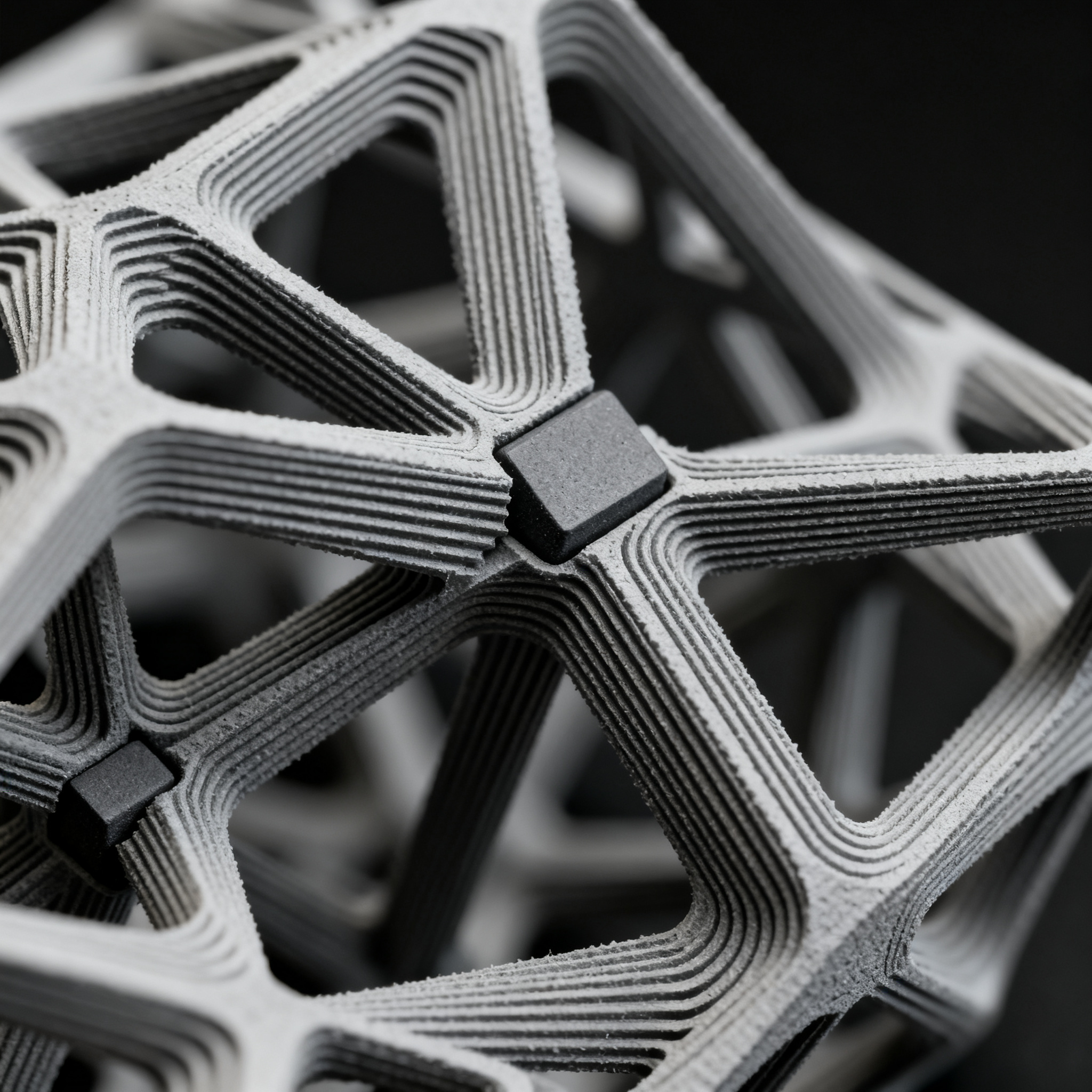
3D lattice structures use geometries designed to modify the mechanical response under load. Struts can be made as rods, spheres, or hemispheres, with non-uniform cross-sections along the length.
This geometric asymmetry is intentional. When the structure undergoes deformation, the struts come into contact with deformation-limiting elements positioned at the center of the lattice structure. These elements, more resistant than the surrounding matrix, block further deformation and transform the behavior from flexible to rigid.
- Variable-section struts optimized to resist bending and compression
- Central limiting structures with resistance superior to the matrix
- Controlled contact between elements for progressive stiffening
The passage occurs in two phases: initially the matrix absorbs the load through the Poisson effect. Subsequently, the struts contact the limiting structure, which offers much greater resistance. This design confers high ultimate resistance because the struts remain intact and undergo supported bending rather than instability.
Role of additive production
3D printing allows the integration of multiple functions into a single component, optimizing stiffness and performance.
Additive manufacturing makes it possible to create complex geometries that are impossible with traditional techniques. All the components discussed – struts, limiting structures, conductive layers, and insulating layers – can be produced with AM techniques.
The struts can be formed without a uniform section and with axial asymmetry. The limiting structures can take any shape, including non-symmetric geometries with specific orientation. This design freedom allows for optimization of resistance to instability and the final failure mode.
Transformation process
- Elastic phase: the matrix deforms by absorbing energy through the Poisson effect.
- Contact: the struts reach the central limiting structure.
- Stiffening: The constraining structure blocks further deformations, drastically increasing stiffness.
Constraining structures can themselves be composite to improve energy absorption. In some cases, they are fixed to one or more struts to precisely control the transition point from flexible to rigid.
Composite materials and safety
The addition of fillers and flame retardants modulates stiffness and energy response without compromising structural integrity.
Material properties are selected to achieve specific performance in combination with geometry. For struts, the relevant properties are: flexural and compressive strength, elastic modulus, hardness, ductility, and toughness. For the matrix: resilience, viscosity, and deformation capacity.
The matrix is typically made with materials of lower modulus and higher toughness compared to the struts. This contrast allows for controlled initial deformation before stiffening.
| Component | Key properties | Function |
|---|---|---|
| Struts | High resistance, rigidity | Structural support |
| Matrix | Low rigidity, high toughness | Energy absorption |
| Limiting structure | Strength greater than the matrix | Deformation blocking |
For applications requiring fire resistance, the matrix, studs, and limiting structures can be made with flame-retardant materials. Suitable materials include tetrabromobisphenol A (TBBPA), hexabromocyclododecane (HBCD), antimony oxide, and organic phosphates such as triphenyl phosphate.
The integration of flame retardants directly into the 3D structure allows for use in fire-resistant assemblies without compromising the designed mechanical properties.
Integrated design for controlled performance
The transformation from flexible to rigid is the result of an integrated design of geometry, process, and material. Each element contributes to the final behavior: the geometry of the struts controls the mode of deformation, additive manufacturing allows for optimized shapes, and materials modulate the energy response.
The control of ultimate strength and failure mode is achieved through the design of limiting structures. Their shape, position, and mechanical properties determine when and how the transition from flexible to rigid behavior occurs.
Explore design parameters to optimize your 3D structures based on load and safety requirements. The combination of variable geometry, additive manufacturing, and composite materials offers unprecedented control over mechanical behavior.
article written with the help of artificial intelligence systems
Q&A
- What are the two main phases of the transformation process from flexible to rigid in the described 3D structures?
- Initially, the matrix deforms elastically, absorbing energy through the Poisson effect. Subsequently, the struts come into contact with the central limiting structure, which, being stronger than the matrix, blocks further deformation and transforms the behavior from flexible to rigid.
- How does additive manufacturing contribute to the realization of these structures?
- 3D printing allows for the integration of multiple functions into a single component and the realization of complex geometries impossible with traditional techniques. This enables the production of struts with non-uniform cross-sections and axial asymmetry, as well as limiting structures with optimized shapes and specific orientation.
- Why must the matrix and struts have different mechanical properties?
- The matrix is typically made with materials of lower modulus and higher toughness compared to the struts, allowing for controlled initial deformation and energy absorption. The struts, on the other hand, require high bending and compression strength to support the load and remain intact until contact with the limiting structures.
- What is the role of the central limiting structures in the final mechanical behavior?
- The central limiting structures have higher strength than the surrounding matrix and block deformations when the struts come into contact with them. Their shape, position, and mechanical properties determine the exact transition point and the mode of final failure of the structure.
- How is fire resistance guaranteed without compromising the designed mechanical properties?
- The matrix, struts, and limiting structures can be made by directly integrating flame retardants such as TBBPA, HBCD, antimony oxide, or organic phosphates. This direct integration into the 3D structure allows for the creation of fire-resistant assemblies while maintaining the designed mechanical performance unchanged.