Calibration that self-corrects during printing?
Industrial 3D printing is becoming smarter thanks to systems that correct the production process in real time, reducing errors and waste.
Until recently, discovering a defect on a 3D-printed turbine meant starting from scratch. The piece ended up as scrap, parameters were adjusted, and the process restarted. A costly cycle that slows production and wastes precious materials.
Today two patented approaches are changing the rules. One uses high-resolution cameras to correct the laser position without touching the machine. The other prints test elements during the process to adjust parameters before it is too late.
Calibration without touching anything
A system based on high-resolution imaging allows real-time correction of the laser position, eliminating the need for manual calibrations.
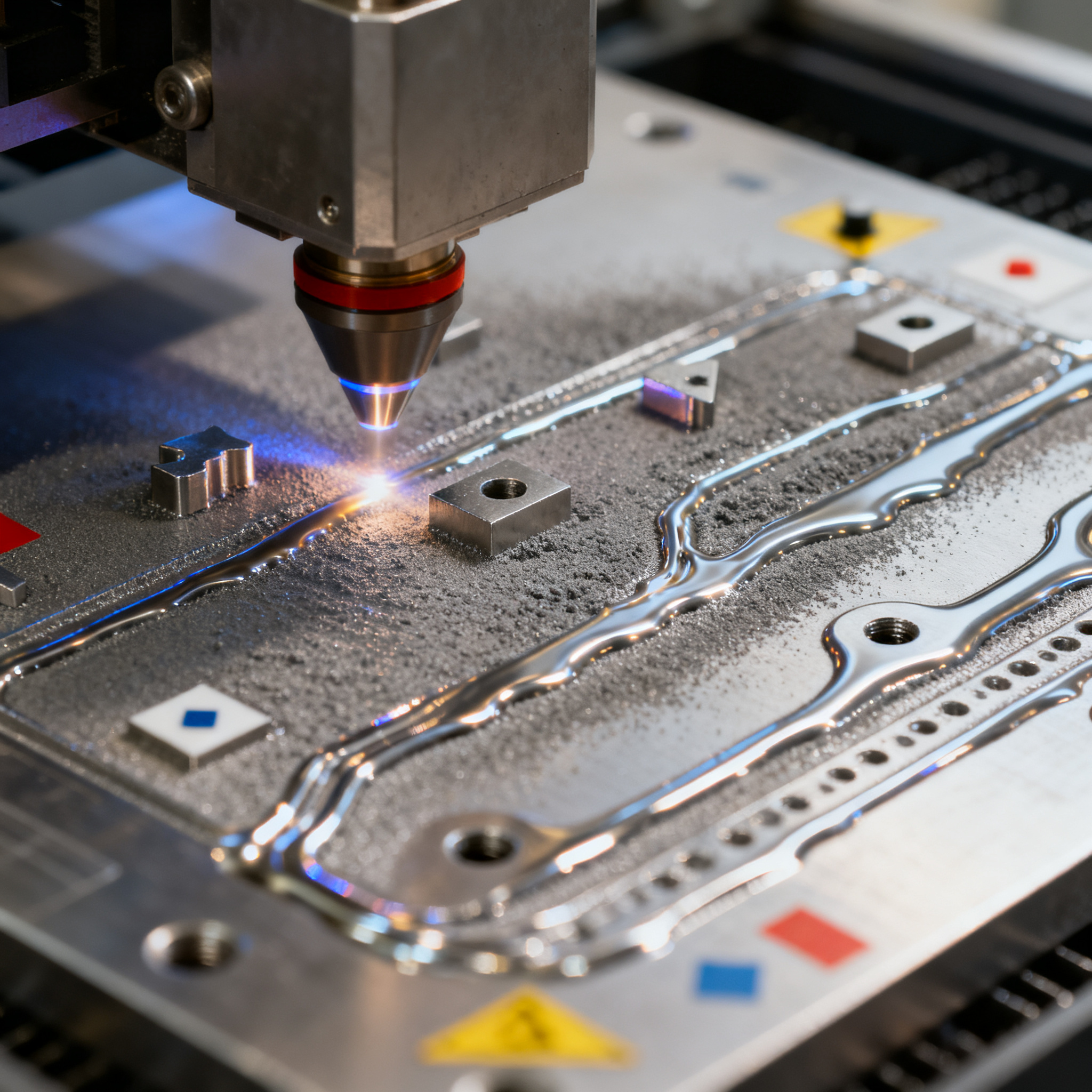
The patent “Scanner Calibration Using High Resolution Imaging Process Monitoring System” proposes an automatic method. A camera captures images of the build plane during printing. On that plane are placed fiducial markers, fixed reference points.
The system processes the images to eliminate optical distortions. Then it compares the actual position of the markers with the nominal position in the machine's coordinate system. From this comparison, it generates a transfer function that automatically corrects the laser trajectory.
- High-resolution camera monitors fiducial markers on the print bed
- Automatic correction of the image’s distortions
- Calibrazione del laser senza intervento dell’operatore
In traditional machines, calibration requires scheduled stops and manual interventions. With this system, the machine self-corrects while working. It is particularly useful for complex geometries like turbine blades, where even small deviations compromise performance.
The patent does not specify how often the correction occurs. Presumably, it depends on the image acquisition frequency and the system's processing speed.
Correct while printing
Instead of waiting until the end of the print to discover an error, new methods adapt process parameters on the fly.
The patent “System and Method for Real-Time \/ In Process Quality Assurance” introduces a different approach. The system prints calibration elements in the free space around the main part. These elements replicate the critical features of the final component, such as cooling holes or thin cavities.
Sensors monitor the production of these test elements. The collected data is compared with a historical database of successful prints. If the system detects deviations, it immediately intervenes by modifying laser power, print speed, or distance between passes.
Correction process
- Positioning: the calibration elements are inserted into the print plan before the critical features of the part.
- Monitoring: sensors record data during the construction of the test elements.
- Comparison: the data is compared with previous successful prints.
- Intervention: if necessary, the system modifies the parameters before printing the final features.
As described in the patent, the method leverages the layer-by-layer nature of additive manufacturing. The calibration elements are positioned lower than the corresponding features in the final part. This ensures sufficient time to observe, analyze, and correct.
The system can print multiple identical elements in sequence. If the first shows problems, the second is produced with correct parameters. The’iteration continues until the data falls within tolerances or the available space runs out.
The patent mentions the possibility of recording the optimized parameters in the machine database. This accelerates future setups for similar components, reducing preparation times.
| Parameter | Traditional approach | Real-time correction |
|---|---|---|
| Correction moment | After printing | During printing |
| Scraps | Complete piece | Only test elements |
| Setup time | Multiple prototype cycles | Reduced with parameter database |
Trade-offs and limitations
Despite the advantages, adoption requires updated hardware and a validation phase for each combination of material and machine.
The imaging-based calibration system described in patent EP4745892A1 requires a high-resolution camera integrated into the machine. Not all industrial printers have this component. An upgrade may be necessary, with costs and installation times to consider.
The patent does not provide details on the system's sensitivity to vibrations or environmental variations. In real production environments, these factors can affect the accuracy of optical measurements.
The real-time correction method described in patent EP4717376A1 could lengthen printing times if many anomalies requiring iterative adjustments are detected.
The second patent emphasizes the need for extensive validation. Each combination of material, geometry, and machine requires the construction of a historical reference database. Without reliable historical data, the system cannot accurately detect deviations.
Patent EP4717376A1 mentions that calibration elements occupy space on the build platform. For very large parts or multiple prints, this could reduce the production capacity per batch.
It is not clear from the sources how complex the software integration is. Both patents involve processing large amounts of data in real time, which could require higher computing capabilities than current systems.
These tools do not completely eliminate human intervention, but shift the focus from post-production corrections to active and intelligent control. Automatic calibration and real-time correction reduce waste and increase repeatability, two critical factors for moving 3D printing from prototyping to mass production.
Evaluate whether your process can benefit from real-time corrections: early adopters could gain months of lead time.
article written with the help of artificial intelligence systems
Q&A
How does the automatic calibration system described in the first patent work?
The system uses an integrated high-resolution camera that captures images of fiducial markers on the build platform. By processing the images it corrects optical distortions, compares the actual position of the markers with their nominal position and generates a transfer function that automatically adjusts the laser trajectory without manual intervention or machine stops.
What is the innovative principle of the second patent to ensure real-time quality?
The method involves printing calibration elements in the free space around the main part, replicating its critical characteristics. Sensors monitor these test elements and the collected data are compared with a historical database; in case of deviations, the system immediately modifies parameters such as laser power and speed before printing the final parts.
What advantages do these systems offer compared to traditional calibration?
They eliminate the need to stop the machine for manual interventions and drastically reduce scrap, since corrections occur during printing rather than after production. They also increase process repeatability and accelerate future setups thanks to the database of optimized parameters.
What are the main limitations and trade-offs in adopting these technologies?
They require updated hardware such as high-resolution cameras and greater computing power, as well as an extensive validation phase for each material and machine combination. Calibration elements take up space on the build platform and corrective iterations could extend printing times.
Why are calibration elements positioned lower than the corresponding features in the final part?
In additive manufacturing, these elements are printed at lower levels than the final critical features. This allows sensor data to be observed and analyzed with the necessary time to adjust the parameters before printing the decisive zones of the part.