How a 3D scanner creates a CAD in 4 steps
Discover how a precision portable 3D scanner like the Creaform HandySCAN 700-Elite transforms a physical object into a CAD model through a fast and accurate process.
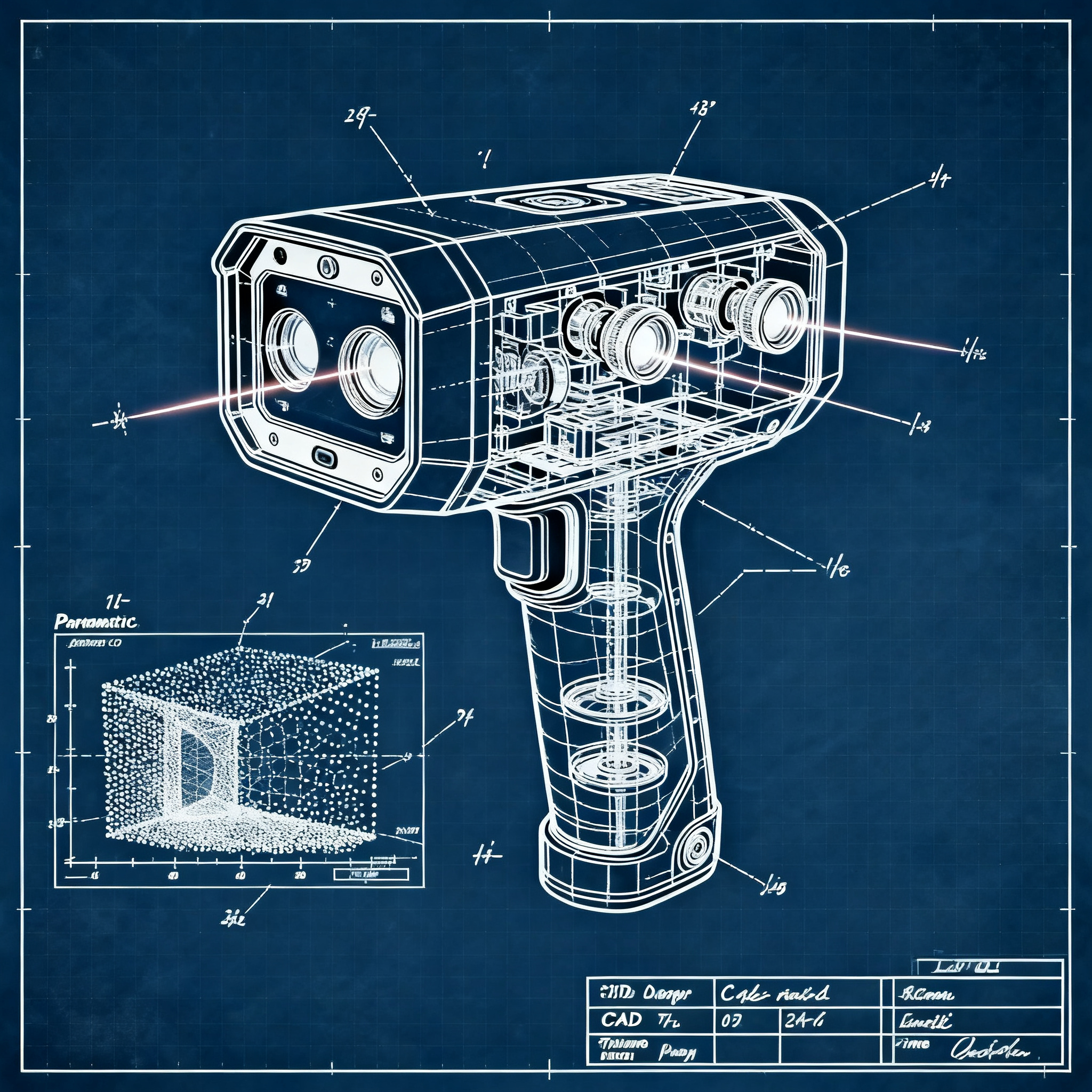
Reverse engineering with professional 3D scanners follows a precise technical workflow that transforms physical geometry into an editable digital model. The process is divided into four distinct phases: high-density laser acquisition, critical surface management, point cloud processing, and parametric CAD output.
High-density geometric acquisition
Laser scanning captures surface geometry with micrometric precision, leveraging multi-laser sensors and integrated cameras.
The Creaform HandySCAN 700-Elite uses 7 laser crosses to capture up to 480,000 points per second. Accuracy reaches 0.030 mm, with volumetric accuracy of 0.020 ± 0.060 mm/m. This data density makes it possible to capture fine details, holes, and complex geometries in just a few minutes.
- Acquisition speed: 480,000 points/second with 7 lasers
- Accuracy: 0.030 mm on a single scan
- Real-time visual feedback: blue (too far), red (too close), green (optimal distance)
- Automatic target detection via artificial intelligence
The system provides real-time visual indicators to maintain the correct distance during scanning. The live mesh visualization allows you to immediately verify surface coverage and the quality of the acquired data.
Critical surface management
Reflective or irregular surfaces are captured using dynamic calibration techniques and adaptive laser patterns.
For difficult surfaces such as deep cavities, reflective areas, or dark components, the system activates the single line laser mode. This mode uses a single lens to penetrate areas inaccessible to the 7 standard lasers. The operator activates this function with a double click on the back of the scanner.
Automatic target tracking eliminates the need for extensive preparation. The system recognizes and follows the markers placed on the part, maintaining alignment even on large or complex objects. Volumetric calibration ensures consistent precision across the entire work area.
Point cloud processing and meshing
Raw data is aligned and converted into a three-dimensional mesh through automatic optimization algorithms.
The VXelements software generates the mesh directly from laser data, without going through an intermediate point cloud. The process takes approximately 1.5 minutes for medium-sized parts. Automatic cleaning algorithms remove noise, close small holes, and optimize the mesh topology.
Data processing flow
- Acquisition: Laser scanning with real-time visual feedback and automatic target tracking.
- Alignment: Automatic merge of multiple scans based on reference markers placed on the part.
- Mesh generation: Direct conversion into an optimized triangular mesh, with automatic cleaning of imperfections.
- Verification: Quality control with deviation maps and identification of critical areas to rescan.
The Smart Resolution function automatically adapts the mesh density based on the local complexity of the geometry. Areas with fine details receive higher resolution, while flat surfaces are simplified to optimize file size.
CAD output and parametric redesign
The final model is ready for use in CAD environments, with controlled tolerances and compatibility with industry-standard formats.
The mesh file is exported in STL or OBJ format for import into reverse engineering software such as Geomagic Design X or VXmodel. The Auto Segment Wizard analyzes the mesh and automatically divides it into geometric regions: planes, cylinders, spheres, and complex surfaces.
| Workflow phase | Typical time | Output |
|---|---|---|
| Part preparation | 5-10 minutes | Object with positioned targets |
| Laser scanning | 2-5 minutes | Multi-view raw data |
| Mesh generation | 1-2 minutes | Clean STL/OBJ file |
| CAD modeling | Hours-days | Editable parametric model |
Sketch tools project profiles onto the mesh to trace 2D geometries with intelligent snapping. The revolution, extrusion, and boundary surface functions reconstruct solid features. Real-time deviation analysis compares the CAD model with the original scan, highlighting deviations beyond tolerance.
The final CAD model is ready for parametric modifications, topological optimization, or preparation for additive manufacturing. Export formats include STEP, IGES, and Parasolid for full compatibility with major industrial design environments.
The final accuracy of the CAD model depends not only on the scanner's precision, but also on the quality of segmentation and the correct interpretation of the design intent. Complex surfaces may require manual decisions on draft, parting line, and functional tolerances.
Conclusion
The reverse engineering process with professional 3D scanners is a precise and repeatable technical workflow, ideal for advanced industrial applications. The combination of high-speed laser acquisition, automatic processing, and CAD integration drastically reduces time compared to traditional methods.
Do you want to replicate this process in your laboratory? Start with a certified metrology scanner and dedicated post-processing software. The learning curve is short thanks to guided workflows and real-time visual feedback.
article written with the help of artificial intelligence systems
Q&A
What are the four phases of the reverse engineering process described in the article?
The process is divided into four distinct phases: high-density laser acquisition, management of critical surfaces, point cloud processing, and parametric CAD output. Each phase contributes to transforming physical geometry into an editable digital model.
What are the acquisition performance specifications of the Creaform HandySCAN 700-Elite?
The scanner uses 7 laser crosses to capture up to 480,000 points per second with an accuracy of 0.030 mm on a single scan. The volumetric accuracy reaches 0.020 ± 0.060 mm/m, allowing fine details to be acquired in a few minutes.
How does the real-time visual feedback work during scanning?
The system provides color-coded indicators that guide the operator to the optimal distance: blue indicates the scanner is too far, red too close, and green the correct distance. This allows immediate verification of surface coverage and the quality of the acquired data.
How are reflective, dark, or deep cavity surfaces handled?
For these critical surfaces, the system activates a single laser line mode, which uses a single laser beam to penetrate areas inaccessible to the standard 7 laser crosses. The operator activates this function with a double-click on the back of the scanner.
What is the advantage of the VXelements software in data processing?
The VXelements software directly generates a three-dimensional mesh from raw data, without going through an intermediate point cloud. The process occurs through automatic optimization algorithms that align and convert the laser data.
What is the purpose of automatic target tracking during scanning?
Automatic tracking eliminates the need for extensive part preparation, as the system recognizes and follows the markers placed on the object. This maintains alignment even on large objects or with complex geometries, ensuring constant precision.